LD Archive
MOST Head Unit
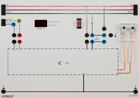
LD DIDACTIC GmbHControl unit for generating the system clock of a MOST data bus system. In conjunction with the CAN gateway 7395861 and the MOST PC USB interface 7402013, a complete MOST ring can be set up (without multimedia functionality!). The unit has an optical display of the ring break diagnosis line and a 7-segment display for showing the node address. The two fibre-optic cables are connected to the other ring in a Plexiglas coupler. This allows the communication setup to be observed and faults to be installed.
General features:
Control unit for MOST system clock generation
Optical interface for fibre optics
Error simulation on fibre optics
Error simulation on CAN bus lines
Display of the node address
High-speed CAN bus connection
Ring-break diagnostic line according to ECL standard
Optical display of the ring break diagnosis status
Fault simulation on the ring-break diagnostic line
Self-diagnostic capability
Self-diagnosis and troubleshooting:
The unit is self-diagnostic-capable, e.g. via the CAN+USB diagnostic interface 7379803, with the following options:
Read out error memory
Display measured values
Carry out actuator test
Control unit adaptation
Ring break diagnosis
Error switching:
Various errors can be applied to the fibre optics. Among other things, it is possible to insert a fault that can only be found with the help of the "-3 dB" setting of the ring break diagnosis!
The ring break diagnostic line itself can be subjected to errors directly at the unit, which can lead to restrictions or failure of this line.
CAN bus errors such as a missing or incorrect terminating resistor can also be caused directly at the unit.
Data bus analysis:
In connection with the MOST PC USB interface 7402013, the optical signals can be recorded with the oscilloscope 739007. The control data can be recorded and evaluated on the PC via the integrated USB interface.
A high-speed CAN bus connection can be established to the CAN gateway 7395861 and examined oscilloscopically.
Compatibility:
The device is compatible with the MOST DAB Radio 7402014. It can be used to expand the training panel Comfort, 739586, to include the MOST and the high-speed CAN bus.
The front panel of the unit is printed in colour so that a visual assignment of the CAN and MOST bus systems is easy. To simplify the experimental setup, the power supply T30 and 15, the ring break diagnostic line as well as the ground are connected through from left to right on 4 mm safety sockets.
- Supply voltage: 13.8 V=
- Maximum current consumption: 2 A
- MOST system clock: 22.5 MHz
- CAN bus: Highspeed, 500 kbaud
| Type | Title | Actions |
|---|---|---|
| [740 2015] MOST Head Unit (de) |
Share Document
Here you can create a temporary link that allows your students to open the document without logging in.
Here the feature is explained in a video.

Copy the link and send it to your students in any way. Or show them the QR code. This way your students can easily open the document.